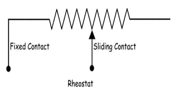
A potentiometer is a three-terminal variable resistor whose resistance may be manually adjusted to regulate the flow of current. A voltage divider with adjustable steps is a potentiometer.
An electronic component that is passive is a potentiometer. By adjusting the location of a sliding contact across a constant resistance, potentiometers function. The output voltage of a potentiometer is the difference in voltage between the fixed and sliding contacts, as shown below. The full input voltage is applied throughout the entire length of the resistor in a potentiometer.
The two input source terminals of a potentiometer are fixed to the resistor’s end. The sliding contact is moved along the resistor on the output side to change the output voltage.
As opposed to a rheostat, this one has one end that is fixed and the sliding terminal is wired into the circuit, as seen in the illustration below.

This extremely basic tool is used to calibrate ammeters, voltmeters, and watt meters as well as to compare the emf of two cells. A potentiometer’s fundamental operating concept is relatively straightforward. Let’s say we have a galvanometer connecting two batteries in parallel. According to the diagram below, the positive and negative battery terminals are connected via a galvanometer, as well as the negative and positive battery terminals.
If both battery cells’ electric potentials are exactly the same in this case, there is no circulating current in the circuit and no deflection on the galvanometer as a result. This phenomena is what drives the potentiometer’s operating principle.

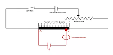
Now consider a different circuit, as illustrated in the diagram below, where a battery is linked across a resistor using a switch and a rheostat.
The electrical resistance of the resistor is constant along its whole length.
As a result, the resistor’s voltage drop remains constant along its whole length. Let’s say that changing the rheostat causes a voltage drop of v volts per resistor unit.
Now, a standard cell’s positive terminal is attached to point A on the resistor and its negative terminal is attached to a galvanometer. As seen in the above diagram, a sliding contact connects the other end of the galvanometer to the resistor. A position like B, where there is no current flowing through the galvanometer and thus no deflection in the galvanometer, is obtained by adjusting this sliding end.
This means that the voltage present between points A and B in the resistor is all that is needed to balance the emf of the standard cell. Now we can write emf of a typical cell E = Lv volt if the distance between locations A and B is L.
In order to measure the voltage between two locations (in this case, A and B), a potentiometer does not draw any current from the circuit. A potentiometer’s specialty is that it can measure voltage with the utmost accuracy.


