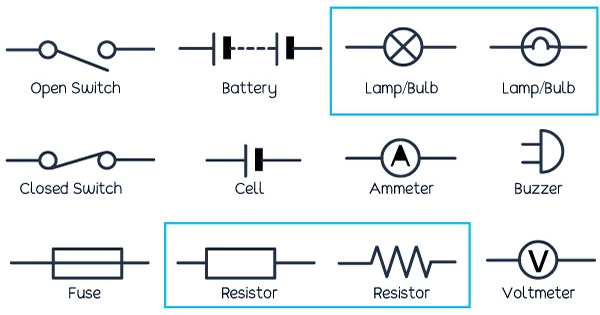
An electrical circuit is graphically represented by a circuit diagram, sometimes referred to as an electrical diagram or an electronic schematic. A circuit is a channel that joins several electrical or electronic components using wires. A schematic of an electrical circuit’s course and return can be found in electrical systems and components. Simple and identifiable graphics, such as a broken line for a switch or a straight line for a wire, are shown on pictorial maps, which are frequently used by laypeople. Advanced experts frequently employ schematic maps, which show the more complex industrial symbols for terminals, amperes, and other electrical components.
Circuit diagrams are crucial because they show the precise layout and progression of the desired electrical circuit. In contrast to a simple layout or wiring diagram, they show the fundamental wiring or circuit connections of the electrical parts inside the electronic device rather than the physical configurations of the circuit. Professionals use an electrical diagram as their reference when creating electronics, electrical systems, and maintaining those systems. Amplified circuit diagrams, electronic circuit diagrams, power circuit diagrams, and power supply diagrams are only a few examples of the diagrams that are labeled according to their intended use.

Diagrams of electrical circuits have evolved along with electric technology. Radios and other vintage electronics once contained enclosures with a twisted network of wires connecting to internal conductors. In order to route tiny grooves or mapped surfaces to the conductors inside the electronic device, plastic circuit boards now come with traces—narrow metallic paths. Although the fundamental idea of paths connecting conductors still holds true, circuit diagrams have developed to reflect the more intricate additions and mappings to contemporary electronics and electrical systems.
An electrical circuit is graphically represented by a circuit diagram, sometimes referred to as an electrical diagram or an electronic schematic. An electrical circuit is graphically represented by a circuit diagram, sometimes referred to as an electrical diagram or an electronic schematic. Circuit diagram symbols used to differ depending on the nation of origin, but they are now universally standardized. The diagrams and their symbols have evolved along with the nature and technology of electronics. For instance, the resistor’s sign was a zigzag line when it was frequently employed as a coil and wrapped to avoid producing inductance. In place of being utilized in this way today, the resistor is shown as an oblong shape with the units of resistance, ohms, printed within to indicate its use as a metal-coated chip or tube.
These diagrams have evolved into a form of instructional tool and resource for fixing electrical devices as electronics have become more prevalent in commonplace everyday objects like coffeemakers, cars, and dishwashers. The path of electrical continuity is depicted in the diagram. This diagram, despite its extensive use of symbols, is just a map showing the connections and path of an electrical circuit, which is a circular channel of electricity.


